
Search This Supplers Products:Spiral Welded PipeOil PipelinePiling PipeAPI 5L PipeStructural PipeLine Pipe
API 5L Pipe Specification(SSAW)
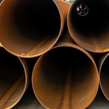


- group name
- Spiral Welded Pipe for Gas Transmission
- Min Order
- 5 ton
- brand name
- Cangzhou Spiral Steel Pipe Manufacturers
- model
- API 5L Pipe
- Nearest port for product export
- Tianjin Port, Port of Tangshan
- Delivery clauses under the trade mode
- FOB, CFR, CIF, EXW, FCA
- Acceptable payment methods
- T/T, L/C
- update time
- Thu, 10 Sep 2026 20:59:14 GMT
Packging & Delivery
-
Min Order5 ton
Briefing
API 5L pipes are carbon steel pipes used for oil and gas transmissions.
Detailed
API 5L Pipe Specification(SSAW) (46th Edition Updated on 2026)
API 5L pipe is your ideal carbon steel pipe material, which can be divided into two types: welded steel pipe and seamless steel pipe. The grades include: B, X42, X46, X52, X56, X60, X65, X70, and X80; Specification grade: PSL1/PSL2, suitable for onshore, offshore, and sulfur-containing environments. In this type of steel pipe, API 5L spiral welded pipe occupies an important position. As a professional manufacturer, Cangzhou Spiral Welded Pipe Group is equipped with CNAS certified laboratories, 13 production lines, and Asia's first 30 meter SSAW unit. We provide one-stop service from raw materials to finished products, ensuring that every steel pipe you receive can operate stably and reliably in your long-distance oil, gas, and water transportation projects.
API 5L Pipe Supply Range (SSAW)
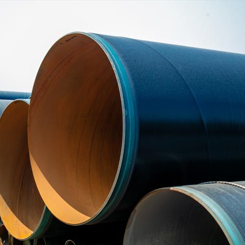
Why Choose WuZhou Brand API 5L Pipe
Grade: B, X42, X46, X52, X56, X60, X65, X70, X80
Outer Diameter: 219-3620mm(8.62-142.52 inch)
Specification Level: PSL1 PSL2 onshore and offshore sour services
Thickness: 6-25.4mm
Thickness Schedule:SCH 40, STD, SCH80, XS, SCH 160
Making Process: SSAW
Pipe End: Beveled ends, Plain ends
Length: SRL, DRL, 20FT (6m), 40FT (12m), or custom 1-30m.
Pipe End Protection:Plastic or iron caps optional.
Surface Treatment: Bare Painted Oiled FBE, 3PE (3LPE) ,3PP,CWC (Concrete Weight Coated) CRA Clad or Lined
Test: X-ray /Ultrasonic Testing/hydrostatic test,etc
Certification: API 5L CE ISO9001 CNAS ,etc
APL 5L Pipe Standard Scope
Simply put, API 5L (46th Edition) is the carbon steel pipe standard you rely on when transporting oil, gas, water, steam, or slurry. Our spiral-welded steel pipes fully comply with this specification and are available in PSL1 and PSL2 grades, with lengths customizable up to 30 meters. Whether your project is onshore or offshore, we can deliver the steel pipes you trust.
Manufacturing Process
1. Raw material inspection: Firstly, strict physical and chemical inspection is carried out on the selected hot-rolled steel coils to ensure that they meet the requirements of API 5L standard for chemical composition and mechanical properties.
2 steel coils are uncoiled and leveled to prepare for subsequent processes.
3. Milling and Forming: The edge of the flattened steel strip is milled to produce precise grooves, which is a key step in ensuring the quality of the weld seam. Afterwards, the steel strip is continuously rolled into a spiral tube through a spiral forming machine.
Welding: This is the core process. Double sided submerged arc welding (SAW) technology is used to weld the inner and outer sides of the pipe, forming a spiral weld seam. This welding method has deep penetration, high efficiency, and can form reliable welds. Welding parameters, such as weld seam gaps, will be strictly controlled.
5 Testing: After welding is completed, a series of strict quality inspections will be carried out. This includes 100% online continuous X-ray automatic testing (UT) of welds, as well as manual use of ultrasonic waves to recheck critical areas (such as steel plate butt welds) to ensure no internal defects. Each steel pipe will undergo a hydrostatic test to verify its compressive strength.
6. Processing and protection of pipe ends. The pipe end will be processed to ensure the perpendicularity of the end face and the accuracy of the groove angle, making it easy to weld on site. Cover the interior of the pipeline with a plastic cap to protect it.
Delivery Conditions for Each API 5L Grade
The steel grades of API 5L are from Gr. B, X42, X46, X52, X56, X60, X65, X70, X80, in order from left to right. As the steel grade continues to increase, their carbon equivalent control becomes increasingly strict and their mechanical properties become higher. Even more interestingly, under the same steel grade, there are many differences in chemical composition between spiral welded pipes and seamless steel pipes. For example: For welded pipes, the API 5L standard imposes tighter limits on carbon and sulfur to ensure weldability.
Under different delivery conditions, We offer pipes in a range of metallurgical states to suit your project needs: as-rolled, normalizing rolled, thermomechanical rolled, normalizing formed, normalized, normalized and tempered, and quenched and tempered.
| Table 1 - Pipe grades, steel grades and acceptable delivery conditions | ||
| PSL | Delivery Condition | Pipe Grade/Steel Grade a b |
| PSL1 | As-rolled, normalizing rolled, normalized or normalizing formed | L175 or A25 |
L175P or A25P | ||
L210 or A | ||
As-rolled, normalizing rolled, thermomechanical rolled, thermomechanicalformed, normalizing formed, normalized, normalized and tempered; or, ifagreed, quenched and tempered for SMLS pipe only | L245 or B | |
L290 or X42 | ||
L320 or X46 | ||
L360 or X52 | ||
L390 or X56 | ||
L415 or X60 | ||
L450 or X65 | ||
L485 or X70 | ||
PSL2 | As-rolled | L245R or BR |
L290R or X42R | ||
Normalizing rolled, normalizing formed, normalized or normalized and tempered | L245N or BN | |
L290N or X42N | ||
L320N or X46N | ||
L360N or X52N | ||
L390N or X56N | ||
L415N or X60N | ||
Quenched and tempered | L245Q or BQ | |
L290Q or X42Q | ||
L320Q or X46Q | ||
L360Q or X52Q | ||
L390Q or X56Q | ||
L415Q or X60Q | ||
L485Q or X70Q | ||
L555Q or X80Q | ||
L625Q or X90Qc | ||
L690Q or X100Qc | ||
Thermomechanical rolled or thermomechanical formed | L245M or BM | |
L290M or X42M | ||
L320M or X46M | ||
L360M or X52M | ||
L415M or X60M | ||
L450M or X65M | ||
L485M or X70M | ||
L555M or X80M | ||
Thermomechanical rolled | L625M or X90M | |
L690M or X100M | ||
L830M or X120M | ||
a For intermediate grades, the steel grade shall be in one of the following formats: (1) The letter L followed by the specifiedminimum yield strength in MPa and, for PSL 2 pipe, the letter describing the delivery condition (R, N, Q or M) consistent with theabove formats. (2) The letter X followed by a two or three digit number equal to the specified minimum yield strength in 1000 psirounded down to the nearest integer and, for PSL 2 pipe, the letter describing the delivery condition (R, N, Q or M) consistent witthe above formats. b The suffix (R, N, Q or M) for PSL 2 grades belongs to the steel grade. c Seamless only. | ||
API 5L Pipe Data Sheet Specification(SSAW)
The API 5L Pipe Data Sheet Specification (SSAW) includes two very important data tables: the API 5L Spiral Welded Pipe Chemical Composition Data Table and the API 5L Spiral Welded Pipe Mechanical Properties Data Table. Wuzhou Spiral Welded Pipe strictly adheres to these standard specifications in its custom manufacturing process.
Chemical Composition
Chemical composition for PSL1 line pipe with wall thickness ≤ 25.0 mm (0.984 inches)
API 5L Pipe Datasheet in PDF
Chemical Composition | ||||||||
Steel Grade | Wall Thickness ≤ 25.0 mm (0.984 in) | |||||||
Mass fraction, based upon heat and product analyses | ||||||||
% | ||||||||
C | Mn | P | S | V | Nb | Ti | ||
max | max | min. | max | max | max | max | max | |
Weld(SSAW) Pipe | ||||||||
L175 or A25 | 0.21 | 0.6 | - | 0.030 | 0.030 | - | - | - |
L175P or A25P | 0.21 | 0.6 | 0.045 | 0.080 | 0.030 | - | - | - |
L210 or A | 0.22 | 0.9 | - | 0.030 | 0.030 | - | - | - |
L245 or B | 0.26 | 1.2 | - | 0.030 | 0.030 | c,d | c,d | d |
L290 or X42 | 0.26 | 1.3 | - | 0.030 | 0.030 | d | d | d |
L320 or X46 | 0.26 | 1.4 | - | 0.030 | 0.030 | d | d | d |
L360 or X52 | 0.26 | 1.4 | - | 0.030 | 0.030 | d | d | d |
L390 or X56 | 0.26 | 1.4 | - | 0.030 | 0.030 | d | d | d |
L415 or X56 | 0.26 | 1.4 | - | 0.030 | 0.030 | f | f | f |
L450 or X65 | 0.26 | 1.45 | - | 0.030 | 0.030 | f | f | f |
L485 or X70 | 0.26 | 1.65 | - | 0.030 | 0.030 | f | f | f |
a. Cu ≤ 0,50 %; Ni ≤ 0,50 %; Cr ≤ 0,50 % and Mo ≤ 0.15% b. For each reduce of 0.01% Carbon Max, an increase of 0.05% of maximum Mn is permited, up to a maximum of 1.65 for grade ≥B or L245, but ≤X52 or L360; Up to max 1.75% for grades above L360 or X52, but below L485 or X70; And up to 2.00% max for grade X70 or L485. c. Unless otherwise agreed, Nb + V ≤ 0.06%. d.Nb +V+Ti≤0.15%. e. Unless otherwise agreed. f. Unless otherwise agreed, Nb + V + Ti ≤ 0.15%. g. B shall be not added in on purpose, and maximum B is 0.001%. | ||||||||
API 5L PSL2 Pipe chemical properties:
Chemical composition for API 5L PSL2 pipe with t ≤ 25.0 mm (0.984 inches)
API 5L Pipe Datasheet in PDF
Steel Grade | Mass fraction, based upon heat and product analyses | Carbon | |||||||||
% maximum | |||||||||||
Cb | Si | Mnb | P | S | V | Nb | Ti | Other | CEiiw | CEpcm | |
Seamless And Weld(SSAW) Pipe | |||||||||||
L245R or BR | 0.24 | 0.40 | 1.20 | 0.025 | 0.015 | c | c | 0.04 | e,l | 0.43 | 0.25 |
L290R or X42R | 0.24 | 0.4 | 1.20 | 0.025 | 0.015 | 0.06 | 0.05 | 0.04 | e,l | 0.43 | 0.25 |
L245N or BN | 0.24 | 0.40 | 1.20 | 0.025 | 0.015 | c | c | 0.04- | e,l | 0.43 | 0.25 |
L290N or X42N | 0.24 | 0.4 | 1.20 | 0.025 | 0.015 | 0.06 | 0.05 | 0.04 | e,l | 0.43 | 0.25 |
L320N or X46N | 0.24 | 0.40 | 1.40 | 0.025 | 0.015 | 0.07 | 0.05 | 0.04 | d,e,l | 0.43 | 0.25 |
L360N or X52N | 0.24 | 0.45 | 1.40 | 0.025 | 0.015 | 0.10 | 0.05 | 0.04 | d,e,l | 0.43 | 0.25 |
L390N or X56N | 0.24 | 0.45 | 1.40 | 0.025 | 0.015 | 0.10 | 0.05 | 0.04 | d,e,l | 0.43 | 0.25 |
L415N or X60N | 0.24f | 0.45 | 1.4f | 0.025 | 0.015 | 0.10 | 0.05 | 0.04 | g,h,l | as agreed | |
L245Q or BQ | 0.18 | 0.45 | 1.40 | 0.025 | 0.015 | 0.05 | 0.05 | 0.04 | e,l | 0.43 | 0.25 |
L290Q or X42Q | 0.18 | 0.45 | 1.4f | 0.025 | 0.015 | 0.05 | 0.05 | 0.04 | e,l | 0.43 | 0.25 |
L320Q or X46Q | 0.18 | 0.45 | 1.40 | 0.025 | 0.015 | 0.05 | 0.05 | 0.04 | e,l | 0.43 | 0.25 |
L360Q or X52Q | 0.18 | 0.45 | 1.50 | 0.025 | 0.015 | 0.05 | 0.05 | 0.04 | e,l | 0.43 | 0.25 |
L390Q or X56Q | 0.18 | 0.45 | 1.50 | 0.025 | 0.015 | 0.07 | 0.05 | 0.04 | d,e,l | 0.43 | 0.25 |
L415Q or X60Q | 0.18 | 0.45 | 1.7f | 0.025 | 0.015 | g | g | g | h,l | 0.43 | 0.25 |
L450Q or X65Q | 0.18 | 0.45 | 1.7f | 0.025 | 0.015 | g | g | g | h,l | 0.43 | 0.25 |
L485QorX70Q | 0.18 | 0.45 | 1.8f | 0.025 | 0.015 | g | g | g | h,l | 0.43 | 0.25 |
L555Q orX80Q | 0.18 | 0.45 | 1.9f | 0.025 | 0.015 | g | g | g | i,j | as agreed | |
L625Q orX90Q | 0.16 | 0.45 | 1.90 | 0.020 | 0.010 | g | g | g | j,k | as agreed | |
L690Q or X100Q | 0.16 | 0.45 | 1.90 | 0.020 | 0.010 | g | g | g | j,k | as agreed | |
Welded Pipe | |||||||||||
L245M or BM | 0.22 | 0.45 | 1.20 | 0.025 | 0.015 | 0.05 | 0.05 | 0.04 | e,l | 0.43 | 0.25 |
L290M or X42M | 0.22 | 0.45 | 1.30 | 0.025 | 0.015 | 0.05 | 0.05 | 0.04 | e,l | 0.43 | 0.25 |
L320M or X46M | 0.22 | 0.45 | 1.30 | 0.025 | 0.015 | 0.05 | 0.05 | 0.04 | e,l | 0.43 | 0.25 |
L360M orX52M | 0.22 | 0.45 | 1.40 | 0.025 | 0.015 | d | d | d | e,l | 0.43 | 0.25 |
L390 or X56M | 0.22 | 0.45 | 1.40 | 0.025 | 0.015 | d | d | d | e,l | 0.43 | 0.25 |
L415 orX60M | 0.12f | 0.45f | 1.6 | 0.025 | 0.015 | g | g | g | h,l | 0.43 | 0.25 |
L450orX65M | 0.12f | 0.45f | 1.6 | 0.025 | 0.015 | g | g | g | h,l | 0.43 | 0.25 |
L485M orX70M | 0.12f | 0.45f | 1.7 | 0.025 | 0.015 | g | g | g | h,l | 0.43 | 0.25 |
L625 or X90M | 0.12f | 0.45f | 1.85 | 0.025 | 0.015 | g | g | g | i,l | 0.43 | 0.25 |
L555M or X80M | 0.10 | 0.55f | 2.1f | 0.02 | 0.010 | g | g | g | i,l | - | 0.25 |
L690M or X100M | 0.10 | 0.55f | 2.1f | 0.020 | 0.010 | g | g | g | i,j | 0.25 | |
L830M or X120M | 0.10 | 0.55f | 2.1f | 0.02 | 0.010 | g | g | g | i,j | 0.25 | |
a. Based upon product analysis. For seamless pipe with t > 20.0 mm (0.787 in), the CE limits shall be as agreed. The CEIIW limits apply if C > 0.12% and the CEPcm limits apply if C ≤ 0.12%. b. For each reduction of 0.01% below the specified maximum for C, an increase of 0.05% above the specified maximum for Mn is permissible, up to a maximum of 1.65% for grades ≥ L245 or B, but ≤ L360 or X52; up to a maximum of 1.75% for grades > X52, but ≤ L485 or X70; up to a maximum of 2.00% for grades ≥ L485 or X70, but ≤ L555 or X80; and up to a maximum of grades > L555 or X80. c. Unless otherwise agreed, Nb + V ≤ 0.06%. d. Nb + V + Ti ≤ 0.15%. e. Unless otherwise agreed, Cu ≤ 0.50%; Ni ≤ 0.30%; Cr ≤ 0.30%; and Mo ≤ 0.15%. f. Unless otherwise agreed. g. Unless otherwise agreed, Nb + V + Ti ≤ 0.15%. h. Unless otherwise agreed, Cu ≤ 0.50%; Ni ≤ 0.50%; Cr ≤ 0.50%; and Mo ≤ 0.50%. i. Unless otherwise agreed, Cu ≤ 0.50%; Ni ≤ 1.00%; Cr ≤ 0.50%; and Mo ≤ 0.50%. j. B ≤ 0.004%. k. Unless otherwise agreed, Cu ≤ 0.50%; Ni ≤ 1.00%; Cr ≤ 0.55%; and Mo ≤ 0.80%. l. For all PSL 2 pipe grades except those grades to which footnote j already applies, the following applies. Unless otherwise agreed, no intentional addition of B is permitted and residual B ≤ 0.001%. | |||||||||||
Chemical Composition for API Sour Pipe
| Chemical composition for API SL Sour Service Pipe with wall thickness 25.0 mm (0.984 in) | |||||||||||
| Steel Grade | Mass fraction, based upon heat and product analyses | Carbon equivalent % maximum | |||||||||
% maximum | |||||||||||
Cb | Si | Mn b | P | S | V | Nb | Ti | Other c,d | CEiiw | CEpcm | |
| Seamless and welded pipes | |||||||||||
L245NS or BNS | 0.14 | 0.40 | 1.35 | 0.020 | 0.003e | 0.05 | 0.04 | g | 0.36 | 0.19h | |
L290NS or X42NS | 0.14 | 0.40 | 1.35 | 0.020 | 0.003e | 0.05 | 0.05 | 0.04 | - | 0.36 | 0.19h |
L320NS or X46NS | 0.14 | 0.40 | 1.40 | 0.020 | 0.003e | 0.07 | 0.05 | 0.04 | g | 0.38 | 0.20h |
L360NS or X52NS | 0.16 | 0.45 | 1.65 | 0.020 | 0.003e | 0.10 | 0.04 | 0.04 | g | 0.43 | 0.22h |
L245QS or XQBS | 0.14 | 0.40 | 1.35 | 0.020 | 0.003e | 0.04 | 0.04 | 0.04 | - | 0.34 | 0.19h |
L290QS or X42QS | 0.14 | 0.40 | 1.35 | 0.020 | 0.003e | 0.04 | 0.05 | 0.04 | - | 0.34 | 0.19h |
L320QS or X46QS | 0.15 | 0.45 | 1.40 | 0.020 | 0.003e | 0.05 | 0.05 | 0.04 | - | 0.36 | 0.20h |
L360QS orX52QS | 0.16 | 0.45 | 1.65 | 0.020 | 0.003e | 0.05 | 0.05 | 0.04 | g | 0.39 | 0.20h |
L390QS or X56QS | 0.16 | 0.45 | 1.65 | 0.020 | 0.003e | 0.05 | 0.05 | 0.04 | g | 0.40 | 0.21h |
L415QS or X60QS | 0.16 | 0.45 | 1.65 | 0.020 | 0.003e | 0.05 | 0.05 | 0.04 | g,i,k | 0.41 | 0.22h |
L450QS or X65QS | 0.16 | 0.45 | 1.65 | 0.020 | 0.003e | 0.05 | 0.05 | 0.06 | g,i,k | 0.42 | 0.22h |
L485QS or X70QS | 0.16 | 0.45 | 1.65 | 0.020 | 0.003e | 0.05 | 0.05 | 0.06 | g,i,k | 0.42 | 0.22h |
Welded pipe | |||||||||||
L245MS or BMS | 0.10 | 0.40 | 1.25 | 0.020 | 0.002e | 0.04 | 0.04 | 0.04 | - | - | 0.19 |
L290MS orX42MS | 0.10 | 0.40 | 1.25 | 0.020 | 0.002e | 0.04 | 0.04 | 0.04 | - | - | 0.19 |
L320MS orX46MS | 0.10 | 0.45 | 1.35 | 0.020 | 0.002e | 0.05 | 0.05 | 0.04 | - | - | 0.20 |
L360MS or X52MS | 0.10 | 0.45 | 1.45 | 0.020 | 0.002e | 0.05 | 0.06 | 0.04 | - | - | 0.20 |
L390MS or X56MS | 0.10 | 0.45 | 1.45 | 0.020 | 0.002e | 0.06 | 0.08 | 0.04 | g | - | 0.21 |
L415MS or X60MS | 0.10 | 0.45 | 1.45 | 0.020 | 0.002e | 0.08 | 0.08 | 0.06 | g,i | - | 0.21 |
L450MS or X65MS | 0.10 | 0.45 | 1.60 | 0.020 | 0.002e | 0.10 | 0.08 | 0.06 | g,i,k | - | 0.22 |
L485MS or X70MS | 0.10 | 0.45 | 1.60 | 0.020 | 0.002e | 0.10 | 0.08 | 0.06 | g,i,k | - | 0.22 |
a. If C > 0.12%, CEIIW limits shall be applied; If C ≤ 0.12%, CEPCM shall be applied. b. For each reduction of 0.01% for maximum C, an increase of 0.05% maximum Mn is permissible, up to a maximum of 0.20%. c. Al ≤ 0.060%; N ≤ 0.012%; Al/N ≥ 2:1 (titanium-killed or titanium-treated steel not applicable); Cu ≤ 0.35% (Cu ≤ 0.10% if agreed); Ni ≤ 0.30%; Cr ≤ 0.30%; Mo ≤ 0.15%; B ≤ 0.0005%. d. For seamless and welded pipes, Ca ≤ 0.006%; For welded pipe if Ca is added by intention unless agreed, Ca/S ≥ 1.5 in case S > 0.0015%. e. For SMLS pipe maximum limit for S could be increased to ≤ 0.008%, and in case welded if agreed to ≤ 0.006%. For higher S content in the welded pipe, lower Ca/S ratios maybe agreed. f. Nb + V ≤ 0.06%, unless otherwise agreed. g. Nb + V + Ti ≤ 0.15%. h. In case seamless pipe, listed CEPCM value could be increased by 0.03. i. Mo ≤ 0.35% in case agreed. j. Cr ≤ 0.45% in case agreed. k. Cr ≤ 0.45% and Ni ≤ 0.50% in case agreed. | |||||||||||
Tensile and Yield strength
API 5L PSL 1 pipe Mechanical propertiesTensile strength, Yeild strength, Elongation
| Pipe Grade | Pipe body of seamless pipes | Weld seam of EW, LSAW,SSAw and COW pipes | ||
| Yield strength | Tensile strength | Elongation(on 50mm or 2 in) | Tensile strength | |
| Rt0.5 | Rm | Af | Rm | |
MPa (psi), min | MPa (psi), min | % minimum | MPa (psi), min | |
L175 or A25 | 175 (25 400) | 310 (45 000) | c | 310 (45 000) |
L175P or A25P | 175 (25 400) | 310 (45 000) | c | 310 (45 000) |
L210or A | 210 (30 500) | 335 (48 600) | c | 335(48600) |
L245 or B | 245 (35 500) | 415 (60 200) | c | 415 (60 200) |
L290 or X42 | 290 (42 100) | 415 (60 200) | c | 415 (60 200) |
L320 or X46 | 320 (46 400) | 435 (63 100) | c | 435 (63 100) |
L360 or X52 | 360 (52 200) | 460 (66 700) | c | 460 (66 700) |
L390 or X56 | 390(56 600) | 490 (71 100) | c | 490 (71 100) |
L415 or X60 | 415 (60 200) | 520 (75400) | c | 520 (75 400) |
L450 or X65 | 450 (65 300) | 535 (77 600) | c | 535 (77 600) |
| L485 or X70 | 485 (70 300) | 570 (82700) | c | 570 (82 700) |
When you're dealing with intermediate grades, you should determine the minimum tensile strength for the pipe body by checking the next higher grade in the table, then subtract the minimum yield strength. For the weld seam, its minimum tensile strength must match what you set for the pipe body—unless footnote a) says otherwise.
| API 5L PSL 2 Pipe Mechanical PropertiesTensile Strength, Yield Strength, Elongation | |||||||
| Pipe Grade | Pipe body of seamless and welded pipes | Weld seam of HFW, SAw and COW pipes | |||||
Yield strength a | Tensile strength a | Ratio a,c | Elongation (on 50 mm or 2 in) | Tensile strength d | |||
Rt0.5 | Rm | Rto.s/Rm | Af | Rm | |||
MPa (psi) | MPa (psi) | % | MPa (psi) | ||||
minimum | maximum | minimum | maximum | maximum | minimum | minimum | |
L245R or BRL245N or BNL245Qor BQL245M or BM | 245(35 500) | 450e (65 300) e | 415(60200) | 655 (95 000) | 0.93 | f | 415(60200) |
L290R or X42R L290N or X42N L290QorX42Q L290M or X42M | 290(42100) | 495(71800) | 415(60200) | 655(95000) | 0.93 | f | 415(60200) |
L320N or X46N L320QorX46Q L320M or X46M | 320(46 400) | 525(76 100) | 435(63 100) | 655 (95 000) | 0.93 | f | 435(63 100) |
L360N orX52N L360Q or X52Q L360M or X52M | 360(52200) | 530(76900) | 460(66700) | 760(110200) | 0.93 | f | 460(66700) |
L390N or X56N L390QorX56Q L390M or X56M | 390(56 600) | 545(79 000) | 490(71100) | 760(110200) | 0.93 | f | 490(71100) |
| L415N or X6ON L415QorX60Q L415Mor X60M | 415(60200) | 565(81900) | 520(75 400) | 760(110200) | 0.93 | f | 520(75400) |
L450Q or X65Q L450M or X65M | 450(65 300) | 600(87000) | 535(77 600) | 760(110200) | 0.93 | f | 535(77 600) |
L485Q or X70Q L485M or X70M | 485(70300) | 635(92 100) | 570(82700) | 760(110200) | 0.93 | f | 570 (82700) |
L555Q orX80Q L555M or X80M | 555(80500) | 705 (102300) | 625(90 600) | 825(119 700) | 0.93 | f | 625 (90 600) |
L625M or X90M | 625(90 600) | 775(112 400) | 695(100 800) | 915(132700) | 0,95 | f | 695(100800) |
L625Q or X90Q | 625(90 600) | 775(112400) | 695(100800) | 915(132 700) | 0,97g | f | 695(100 800) |
L690M or X100M | 690 b(100100)b | 840b(121 800)b | 760(110200) | 990(143 600) | 0,97h | f | 760 (110 200) |
L690Qor X100Q | 690 b(100 100)b | 840b(121 800) b | 760(110200) | 990(143 600) | 0,97h | f | 760 (110 200) |
L830M or X120M | 830b(120 400)b | 1050b(152 300)b | 915(132700) | 1145(166 100) | 0,99h | f | 915(132 700) |
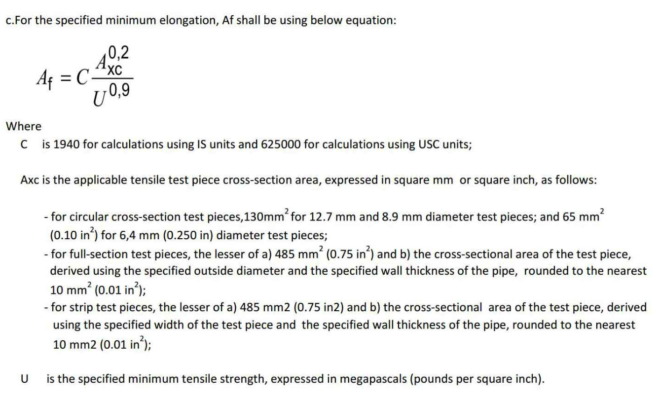
a. For intermediate grades, the difference between specified maximum yield strength and minimum YS shall be as given in the table for the next higher grade, and the difference between specified minimum tensile strength and the specified minimum TS shall be as given in the table for the next higher grade. For intermediate grades up to Grade L320 or X46, the tensile strength shall be ≤ 655 MPa (95 000 psi). For intermediate grades greater than Grade L320 or X46 and lower than Grade L555 or X80, the tensile strength shall be ≤ 760 MPa (110 200 psi). For intermediate grades higher than Grade L555 or X80, the maximum permissible tensile strength shall be obtained by interpolation. For SI units, the calculated value shall be rounded to the nearest 5 MPa. For USC units, the calculated value shall be rounded to the nearest 100 psi. b. For grades > L625 or X90, Rp0,2 applies. c. Above limit applies for pipe with D > 323,9 mm (12.750 in). d. For intermediate grades, the specified minimum tensile strength for the weld seam shall be the same value as was determined for the pipe body using footnote a). e. For pipe requiring longitudinal testing, the maximum yield strength shall be ≤ 495 MPa (71 800 psi). f. The specified minimum elongation, Af, shall be as determined with following equation: A_f = C * A_xC^0.2 / U^0.9 g. Lower values of Rt0,5/Rm may be specified by agreement. h. For grades > L625 or X90, Rp0,2 /Rm applies. Lower values of Rp0,2 /Rm may be specified by agreement. | |||||||
Mechanical Properties for API 5L Sour Service Pipe
| Table H.2-Requirements for the results of tensile tests for sour service pipe in API 5L | |||||||
| Pipe Grade | Yield strength a Rt0.5 MPa(psi) | Tensile strength a Rm MPa(psi) | Ratio b Rto,s/Rm | Elongation (on50 mm or 2 in) Af % | Tensile strength c Rm MPa(psi) | ||
minimum | maximum | minimum | maximum | maximum | minimum | minimum | |
L245NS or BNS L245QS or BQS L245MS or BMS | 245(35500) | 450 (65300) | 415 (60200) | 655 (95000) | 0.93 | e | 415 (60200) |
L290NS or X42NS L290QS or X420S L290MS or X42MS | 290(42100) | 495(71800) | 415 (60200) | 655 (95000) | 0.93 | e | 415(60200) |
L320NS or X46NS L320QS or X46QS L320MS or X46MS | 320 (46400) | 525 (76100) | 435(63100) | 655(95000) | 0.93 | e | 435(63100) |
L36ONS or X52NS L360QS or X52QS L360MS or X52MS | 360(52200) | 530 (76900) | 460(66700) | 760(110200) | 0.93 | e | 460(66700) |
L390QS or X56QS L390MS or X56MS | 390 (56600) | 545 (79000) | 490(71100) | 760(110200) | 0.93 | e | 490(71100) |
L415QS or X60QS L415MS or X60MS | 415(60200) | 565 (81900) | 520(75400) | 760(110200) | 0.93 | e | 520(75400) |
| L450QS or X65QS L450MS or X65MS | 450(65300) | 600 (87000) | 535 (77600) | 760(110200) | 0.93 | e | 535(77600) |
L485QS or X70QS L485MS or X70MS | 485(70300) | 635 (92100) | 570 (82700) | 760(110200) | 0.93 | e | 570 (82700) |
The strength value is the same as PSL2.
API 5L Line Pipe Test Methods
Hydrostatic Test
a. Jointers need not be hydrostatically leveled, provided the pipe segments used in their construction have previously passed a hydrostatic test before joining.
b. Otherwise, the pipe shall endure the hydrostatic test with no leakage from the weld seam or the pipe body.
Bend test
You must ensure that no cracks appear in any part of the sample and that the weld does not open. Also note: for all bend tests, you should take the weld zone to include 6.4 mm (0.25 in) on each side of the fusion line.
Flattening Test
You use the flattening test to check whether the line pipe can deform to the specified size and to reveal any defects. From the stress and deformation response of the specimen, you can determine the pipe's resistance to longitudinal and circumferential cracking, and you can also spot both internal and surface defects.
Guided-bend Test
This experiment is used to evaluate the plasticity and integrity of welded joints. You need to bend the sample taken from the weld seam and observe it carefully.
Qualification criteria: No cracks should appear in any part of the sample, and no cracks should occur in the weld seam.
Key judgment area: When making judgments, you need to evaluate the weld seam and the areas within 6.4mm (0.25 inches) on both sides as the heat affected zone of the weld seam.
Charpy V-Notch Impact Test
For PSL2 grade welded pipes, CVN impact testing is mandatory to verify the fracture resistance of pipeline steel pipes under dynamic loads. You need to sample and test from the following three key locations to comprehensively evaluate resilience:
Pipe Body: Evaluate the toughness of the base metal.
Weld Metal: Evaluate the toughness of the weld center.
Heat affected zone (HAZ): Evaluate the area near the weld where the microstructure changes due to welding thermal cycling, which is one of the weakest areas of toughness.
Drop-Weight Tear Test —Regarding PSL2 welded pipes
For PSL2 welded pipes, you need to perform DWTT. This experiment aims to evaluate the resistance of steel pipes to brittle fracture under high-speed impact, which is crucial for preventing catastrophic brittle cracking of pipelines during service and is a key means of ensuring that fracture toughness meets requirements.
In summary, in addition to basic testing, you need to evaluate the plasticity of the weld seam through guided bending tests, and comprehensively verify the safety margin of the pipe and its weld seam under complex working conditions through CVN impact tests and DWTT drop hammer tear tests (mainly for PSL2 welded pipes).
Surface Conditions, Imperfections, and Visible Defects
You must ensure that all API 5L pipes are free from defects, cracks, sweats, and leaks. In addition, you should be aware of the following specific imperfections that may be considered unacceptable:
->Undercuts in SAW and COW pipes
->Arc burns
->Laminations
->Geometric deviations
->Hard spots
Other surface imperfections — you need to evaluate their depth: if it exceeds 0.125 times the wall thickness, or if it is equal to or less than 0.125 times the wall thickness, you shall refer to Clauses C in API 5L for further acceptance criteria.
API 5L Pipe Sizes and Tolerances
Diameter Tolerances and Out-of-Roundness Limits
Table 10 - Tolerances for diameter and out-of-roundness | ||||||
Specified outside diameter mm (in) | Diameter tolerances b mm (in) | Out-of-roundness tolerances mm (in) | ||||
Pipe except the end a | Pipe end a,b.c | Pipe excopt the end a | Pipe end a.b.c | |||
SMLS pipe | Welded pipe | SMLS pipe | Welded pipe | |||
| < 60,3 (2.375) | - 0,8 (0.031)to + 0,4 (0.016) | -0,8 (0.031) to +0,4 (0.016) | 1,2 (0.048) | 0,9 (0.036) | ||
≥60,3 (2.375) to168,3 (6.625) | ±0,0075D | - 0,4 (0.016) to + 1,6 (0.063) | 0,020 D for D/t≤75: by agreement for D/t>75 | 0,015 D for D/t≤75: by agreement for D/t>75 | ||
| >168,3 (6.625) to 610 (24.000) | ±0,0075D | +0,0075D,but maximum of+3,2 (0.125) | ±0,005D, but maximum of 1,6 (0.063) | 0,020 D | 0,015 D | |
| >610(24.000) to 1422 (56.000) | +0,01 D | ±0,005 D,but maximum of±4,0(0.160) | ±2,0(0.079) | ±1,6 (0.063) | 0,015 D, but maximum of 15 (0.6) for D/t≤75; by agreement for D/t>75 | 0,01 D, but maximum of 13 (0.5) for D/t≤75; by agreement for D/t>75 |
| > 1 422 (56.000) | as agreed | |||||
a The pipe end includes a length of 100 mm (4.0 in) at each of the pipe extremities. b For SMLS pipe, the tolerances apply for ≤ 25,0 mm (0.984 in), and the tolerances for thicker pipe shall be as agreed. c For expanded pipe with D ≥219,1 mm (8.625 in) and for non-expanded pipe, the diameter tolerance and the out-of-roundnesstolerance may be determined using the calculated inside diameter (the specified outside diameter minus two times the specified wallthickness) or measured inside diameter rather than the specified outside diameter (see 10.2.8.3). d For determining compliance to diameter tolerances, the pipe diameter is defined as the circumference of the pipe in anycircumferential plane divided by Pi. | ||||||
Tolerances for wall thickness
| Table 11 - Tolerances for wall thickness | |
| Wall thicknesstmm (in) | Tolerances a mm (in) |
| SMLS Pipe b | |
| ≤4,0 (0.157) | + 0,6 (0.024) -0,5(0.020) |
> 4,0 (0.157) to < 25,0 (0.984) | +0,150t-0,125t |
≥ 25,0(0.984) | + 3,7 (0.146) or + 0,1 t, whichever is the greater - 3,0 (0.120) or - 0,1 t, whichever is the greater |
Welded pipe c.d | |
≤5,0 (0.197) | ±0,5 (0.020) |
>5,0 (0.197)to<15,0 (0.591) | ±0.1t |
≥ 15,0 (0.591) | ±1,5 (0.060) |
a If the purchase order specifies a minus tolerance for wall thickness smaller than the applicable value given in this table, the plustolerance for wall thickness shall be increased by an amount sufficient to maintain the applicable tolerance range. b For pipe with D ≥ 355,6 mm (14.000 in) and t ≥ 25,0 mm (0.984 in), the wall-thickness tolerance locally may exceed the plus tolerance for wall thickness by an additional 0,05 , provided that the plus tolerance for mass (see 9.14) is not exceeded. c The plus tolerance for wall thickness does not apply to the weld area d See 9.13.2 for additional restrictions. | |
Tolerances for pipe lengths
API 5L pipe length tolerances shall be complied as following conditions:
a. Random length shall be delivered as below table 12.
b. Approximate lengths shall be delivered as tolerances of +/- 500 mm.
| Table 12 - Tolerances for random length pipe | |||
| Random length designation m(ft) | Minimum length m(ft) | Minimum average lengthfor each order item m(ft) | Maximum length m(ft) |
| Threaded-and-coupled pipe | |||
| 6(20) | 4,88 (16.0) | 5,33 (17.5) | 6,86 (22.5) |
9(30) | 4,11 (13.5) | 8,00 (26.2) | 10,29 (33.8) |
12 (40) | 6,71 (22.0) | 10,67 (35.0) | 13,72 (45.0) |
Plain-end pipe | |||
6 (20) | 2,74 (9.0) | 5,33 (17.5) | 6,86 (22.5) |
9(30) | 4,11 (13.5) | 8,00 (26.2) | 10,29 (33.8) |
12 (40) | 4,27 (14.0) | 10,67 (35.0) | 13,72 (45.0) |
15 (50) | 5,33 (17.5) | 13,35 (43.8) | 16,76 (55.0) |
18 (60) | 6,40 (21.0) | 16,00 (52.5) | 19,81 (65.0) |
24 (80) | 8,53(28.0) | 21,34 (70.0) | 25,91 (85.0) |
Confirmation List of Key Parameters for API 5L Spiral Welded Pipe
a. Quantity: Calculated in meters or tons, specifying the total number of meters or roots.
b. Grade and usage conditions: PSL1 or PSL2 (N/M/Q/NS/MS/QS), whether in sulfur-containing service, onshore or offshore.
c. Pipe type: Spiral welded pipe (SSAW/HSAW)
d. Reference standard: API 5L (latest version).
e. Steel grades: such as X42, X52, X60, X65, X70, etc.
f. Outer diameter (OD) and wall thickness (WT).
g. Length and Type: Double Random Length, Single Random Length, Fixed Length, or Approximate Length.
h. Attachment: Confirm the applicability of accessories such as pipe end bevel, protective ring, coating, marking, etc. as needed.
Additional information (optional parameters)
According to the specific requirements of the project, you can also add the following information in the purchase order:
Chemical composition requirements for intermediate grade pipelines
Carbon Equivalent (CE) Limit
Diameter or roundness tolerance of special size pipelines
Welding requirements for joints
Type of pipe end (such as groove, flat mouth, etc.)
Defect repair requirements
CVN impact test requirements
DWTT drop hammer tear test requirements
Hardness test requirements
Pipeline marking and pipe end color identification
Specific requirements for other projects
Traceability requirements
For PSL1 pipelines, you should ensure that the manufacturer establishes and implements written procedures to maintain:
a. Furnace number identification - until all relevant chemical analyses are completed and meet regulatory requirements;
b. Test unit identification - until all relevant mechanical performance tests are completed and meet specification requirements.
For PSL2 pipelines, in addition to the above requirements, manufacturers should also establish a traceability system to ensure that the chemical and mechanical performance test results of each pipeline can be traced back to the corresponding testing unit.
API 5L Pipeline History and Milestones
(1) Before the release of API 5L (1834-1927)
In 1834, the first cast iron pipe in the United States was manufactured in Millville, New Jersey.
In 1856, the technology of converter steelmaking was successfully developed.
In 1858, the first oil well was drilled in Tetsville, Pennsylvania.
In 1863, threaded joints were used for pipeline connections; In the same year, the pipeline was made of forged iron and overlapped with furnace welding seams.
In 1893, the first 30 inch diameter lap welded pipe was introduced.
In 1899, the first large-diameter seamless steel pipe with a diameter of 20 inches and a wall thickness of 5/8 inches was introduced.
In 1917, an 11 mile long pipeline was welded using arc welding technology.
In 1919, the American Petroleum Institute (API) was established.
In 1924, direct current or low-frequency resistance welding technology was invented.
In 1925, seamless steel pipes with a diameter of 24 inches were put into use.
In 1927, the development of arc welded pipelines was successful.
After the release of API 5L (1928-2000)
In 1928, API released the first pipeline pipe standard -5L standard, covering furnace butt welded pipes, furnace lap welded pipes, and seamless pipes. The minimum yield strength is 172 MPa (25000 psi) and the maximum yield strength is 310 MPa (45000 psi), including three grades A25, A, and B. The minimum yield strengths are 172 MPa, 207 MPa, and 241 MPa, respectively.
In 1931, it was included in the ERW resistance welded pipe.
In 1933, large-diameter steel pipes were mostly welded using arc ring welding.
In 1944, electric flash welded pipes were added.
In 1946, production of 30 inch single submerged arc welded pipes began.
In 1948, double submerged arc welded pipe (DSAW) was introduced; In the same year, the API 5LX standard was released, covering materials with a minimum yield strength of 289 MPa (42000 psi).
In 1953, X46 and X52 steel grades were added.
In 1962, furnace welded pipes were abolished and the alkaline oxygen converter steelmaking process was adopted.
In 1963, non-destructive testing methods were adopted.
In 1966, X60 steel grade was introduced.
In 1969, additional requirements were added for toughness testing.
In 1973, X70 steel grade was introduced.
In 1983, API 5L and API 5LX merged to form API 5L.
In 1985, X80 steel grade was introduced.
In 2000, a mandatory minimum level of fracture toughness was required.
Overview of the usage of various steel grades before 2000
Before 2000, X70 steel grade pipelines accounted for about 40% of the total pipe usage, while X65 and X60 each accounted for about 30%. Small diameter pipelines mostly used X52 steel grade, with the majority being ERW welded pipes.
API SPEC 5L and ISO 3183
API SPEC 5L 2018 edition is the 46th edition of the API Pipeline Standard.This version was launched in April 2018 and came into effect on May 1, 2019.
In 2007, ISO and API jointly released ISO 3183:2007/API SPEC 5L 44, completing a globally recognized international standard. However, due to the United States' claim of intellectual property rights, API terminated its cooperation with ISO in 2012 and no longer developed standards for ISO. But the latest version of ISO 3183:2012 or API 5L 2012 is still the result of cooperation between the two parties, except for the API logo and European onshore pipeline specifications, all other contents are the same as ISO 3183:2007.
Differences between API 5L 45th edition and previous versions
The main difference between the 45th edition and previous editions is the addition of two appendices: the European onshore pipeline PSL2 pipeline ordering specification (Appendix M) and the relevant equations for threaded connection pipes, guide bends, and CVN test specimens (Appendix P). In terms of other content, apart from adjustments to text expression, there are only slight differences in relevant standards, manufacturing processes, performance specifications, inspection methods, and other aspects. The latest version of API 5L 2012 is more comprehensive and scientific.
API 5L Pipeline Application
Modern API 5L spiral welded steel pipes are made of low-carbon or ultra-low carbon microalloyed steel and are high-quality pipe products with high technical content and added value.
In the past two decades, the production process of spiral welded pipes has integrated multiple advanced technologies in the metallurgical field, achieving quality improvement in every link from steelmaking to forming, welding, and testing.
Currently, pipeline engineering is developing towards large-diameter, high transmission pressure, complex corrosive environments, and thick walled subsea pipelines. Therefore, API 5L spiral welded pipe must have high strength, high toughness, good welding performance, and be able to adapt to acidic and H ₂ S corrosive environments, meeting the requirements of long-term safe service.
Choosing API 5L spiral welded steel pipe provides reliable assurance of strength, toughness, and corrosion resistance for your pipeline project.
